
Most commonly asked Automotive Interview Questions and Answers for Embedded Engineers to grow in their educational and professional journey.
CAN Protocol Interview Questions and Answers :
Q1. What is CAN?
The Controller Area Network (CAN) is a multi-master serial communications protocol. CAN protocol is a robust vehicle bus standard for communication between various electronic devices like Engine Management Systems, Active Suspension, ABS, Gear Control, Lighting Control, Air Conditioning, Airbags, Central Locking, etc. without a host computer. CAN is a message based protocol and not an address based protocol designed originally for multiplex electrical wiring within automobiles to solve wiring complexity and save cost.
Automotive industry uses CAN protocol is widely and nowadays many other areas like industrial automation, medical industry, defense industry, etc. also uses CAN protocol for communication. CAN protocol is developed by Bosch.
CAN protocol is a Carrier-Sense Multiple Access protocol with Collision Detection and Arbitration on Message Priority (CSMA/CD+AMP).
Q2. What are the types of CAN frames?
Answer : There are four types of frames in CAN:
- Data Frame (Widely used frame type)
- Remote Frame
- Error Frame
- Overload Frame
CAN data frame is a frame type that is more widely used than the rest of the frame types.
There are two types of a data frame :
- Standard frame (11-bit Identifier)
- Extended frame (29-bit Identifier)
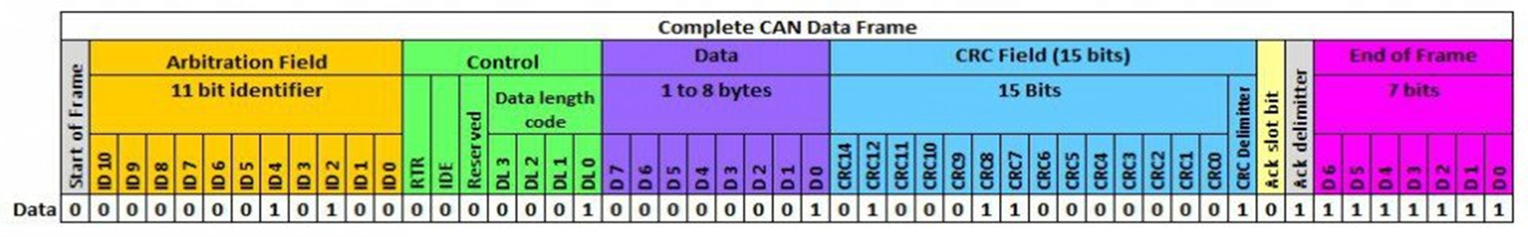
Standard Frame (11-Bit Identifier) :
The CAN Standard frame format is:

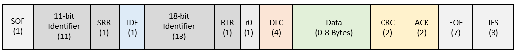
Extended Frame (29-Bit Identifier)
The CAN Extended frame format is:
CAN Frame field details
- SOF – Start of Frame – 1 bit (Dominant)
- Arbitration Field – 11-bit Identifier, 1-bit RTR (or) 11 bit, 1 SRR, 1 IDE, 18 bit, 1 RTR
- Identifier – A message identifier sets the priority of the data frame
- RTR – Remote Transmission Request (data frame or remote frame) (1 bit)
- SRR – Substitute Remote Request
- Control Field – User Defined functions
- IDE – Identifier Extension Bit (standard CAN Identifier with not extension)
- r0 – Reserved bit (for possible use by future standard amendments)
- DLC – The 4-bit data length code (DLC) contains the number of data bytes
- Data Field – Data up to 64 bits of application data
- CRC Field – The 16-bit (15 bits plus delimiter) cyclic redundancy check (CRC) contains the checksum (number of bits transmitted) of the preceding application data for error detection.
- ACK Field – Receivers Acknowledgement
- EOF – End of Frame (7 bit – Recessive)
- IFS – This 7-bit interframe space (IFS) contains the time required by the controller to move a correctly received frame to its proper position in a message buffer area.
Q3. What are the features of the CAN Protocol?
Answer : The list of major features of CAN Protocol are as follows:
- CAN offers Multi-Master communication
- Flexibility in configuration and simple wiring
- Low Cost
- CAN is a message based protocol and not an address based protocol
- Message prioritization through identifier selection
- Built-in Error Detection and fault confinement feature
- Automatic retransmission of corrupted message when bus is idle
Q4. What are the applications of the CAN Protocol?
CAN protocol designed to solve the wiring complexity and communication issues occurs in vehicles.
On the basis of CAN features it is also used in other field as well.
Some Listed applications of CAN Bus are as follows:
- Automotive (Passenger vehicles, Buses, Trucks)
- Industrial and Building automation
- Agricultural Equipment
- Elevators, Escalators
- Medical Instruments and Equipment
- Defense, Aviation industry instruments and equipment’s
- Marine industry instruments and equipment’s
Q5. What is CAN arbitration? What is CSMA/CD in CAN Communication?
CAN arbitration is the process to take control of the bus. CAN node monitors the bus before transmission of the message it is called as Carries Sense.
When two or more than two CAN nodes start transmission then the SOF (Dominant) bit is transmitted from the nodes that are trying to send the messages on the bus this situation is called Multiple Access.
If two nodes start transmitting at the same time then there is a situation of a collision. To solve this problem CAN uses Collision Detection and bitwise arbitration.
Q6. Why CAN is having 120 ohms termination resistor at each end?
Termination resistor (120 ohms) is used to minimize the reflection reference, to reduce noise. To ensure that reflection does not cause communication failure, the transmission line must be terminated.
Q7. Logic used in CAN?
CAN follows Wired AND logic.
Q8. What is the speed of CAN?
CAN speed is 1 Mbps till 40m and if the cable length increases will decrease the speed, due to RLC on the cable.
Q9. If master sends 764 and Slave sends 744 which will get the arbitration?
Starts from MSB, first nibble is same, Master sends 7, slaves also sends 7 the message with more dominant bits will gain the arbitration, lowest the message identifier higher the priority. hence 744 will get the arbitration.
Q10. What type of errors are present in CAN protocol?
Answer : There are five types of errors in CAN protocol.
- BIT Error
- STUFF Error
- CRC Error
- FORM Error
- ACK Error
BIT Error
A CAN node that is sending a bit on the bus also monitors that bit. When the bit value monitored is different than the bit value sent then BIT Error is to be detected.
If there is a ‘recessive’ stuffed bit in ARBITRATION Field or during the ACK SLOT and the ‘dominant’ bit value is monitored then it is an exception for the BIT Error.
STUFF Error
A STUFF Error is to be detected when there are 6 consecutive bits of equal value are detected in the message. It should be addressed using the bit stuffing method.
CRC Error
CAN message also contains the CRC field (result of the CRC calculation done by the transmitter).
When the receiver receives a message it recalculates the CRC using the same calculation method used by the transmitter and if there is a difference between receives CRC and CRC this scenario is treats as CRC Error.
FORM Error
CAN message contains fixed-format fields like CRC Delimiter, ACK Delimiter, End Of Frame, etc. the value of this field is always recessive but when any of this field bit is detects as dominant then it will consider as FORM Error. That means it violates the format of the CAN message.
ACK Error
The ACK field contains two bits ACK SLOT and ACK Delimiter. Whenever a message is transmits ACK SLOT bit is recessive which is transmitted by the transmitter and it will wait for the dominant bit at the same field from the receiver if it doesn’t receive the dominant bit then it will be treated as an ACK Error.
Q11. What is mean by Fault confinement / Error confinement in CAN?
Answer : A node may be in one of the three states: error-active, error-passive, and bus-off. A CAN node uses an error counter to control the transition among these three states.
CAN protocol uses 12 rules to control the increment and decrement of the error counter.
When the error count is less than 128, a node is in an error-active state. If the error count equals or exceeds 128 but is not higher than 255, the node is in an error-passive state. And if the error count equals or exceeds 256, the node is in a bus-off state.
The error-active node will transmit an active-error frame when detecting an error. error-passive node will transmit a passive-error frame when detecting an error. A bus-off node can not take part in bus communication.
Q12. How to calculate CAN Bus Load?
Answer : CAN bus load is nothing but the percentage of bus capacity used.
i.e. Bus Load = ((Used Capacity / Max Capacity) * 100) in percent. Let’s see the below example for better understanding.
Considering standard identifier a CAN frame consists of:
- 1 bit SOF
- 11 bit Identifier
- 1 bit RTR
- 6 bit Control field
- 0-64 bit Data field
- 16 bit CRC field
- 2 bit ACK field
- 7 bit EOF
- 3 bit IFS
- Bit stuffing may be possible we are considering 19 bits to calculation purpose.
Let’s consider we want to send the frames on the bus at a 500kbps baud rate.
- 5 ms : 10 frames
- 10 ms : 5 frames
- 100 ms : 2 frames
considering 8 bytes of Data the total number of bits to transmit are 111 + 19 = 130 bits/frame
- 1/0.005 * 10 * 130 = 2,60,000 bits
- 1/0.010 * 5 * 130 = 65,000 bits
- 1/0.100 * 2 * 130 = 2600 bits
Total no of bits per second = 260000 + 65000 + 2600 = 3,27,600 bits/second
Bus Load = (3,27,600 / 5,00,000) * 100 = 65.52 %