The Controller Area Network (CAN) is a multi-master serial communications protocol. CAN is a message-based protocol and not an address-based protocol.
Automotive industry uses CAN protocol is widely and nowadays many other areas like industrial automation, medical industry, defense industry, etc. also uses CAN protocol for communication.
CAN protocol is a Carrier-Sense Multiple Access protocol with Collision Detection and Arbitration on Message Priority (CSMA/CD+AMP).
History of CAN :
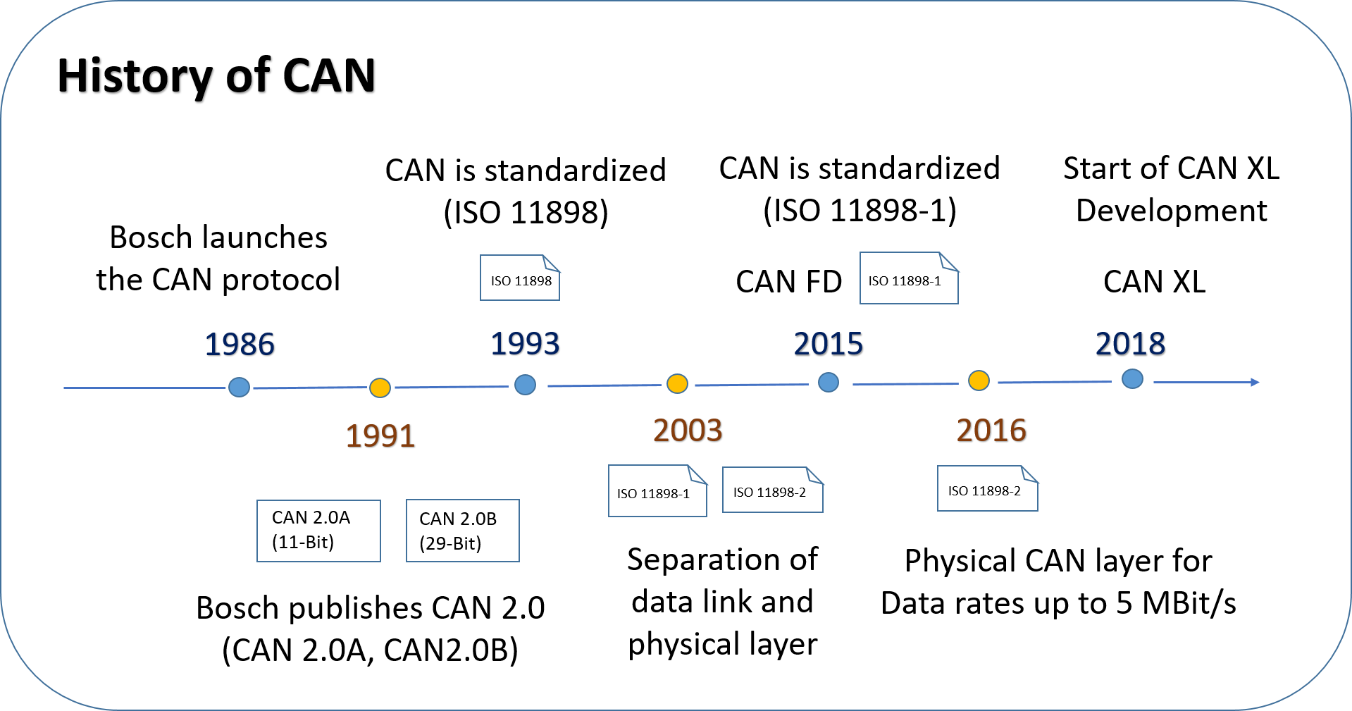
The development of CAN bus started in 1983 at Robert Bosch GmbH. In 1986 at the Society of Automotive Engineers (SAE) conference in Detroit, (Michigan) CAN was officially release.
1991 Bosch published the CAN 2.0 version of CAN and it also has two parts – Part A: CAN 2.0A (11-bit identifier), Part B: CAN 2.0B (29-bit Identifier).
CAN standard ISO 11898 was release in 1993. CAN was further restructure into two parts: ISO 11898-1 which covers the Data Link Layer, and ISO 11898-2 which covers the CAN physical layer for high speed CAN.
2003, ISO 11898 becomes a standard series. 2012, Bosch release CAN FD 1.0 (CAN Flexible Data rate) which was standardize in 2015 (ISO 11898-1).
2016, The physical CAN layer for data rates up to 5 MBit/s standardized in ISO 11898-2. 2018, the development of CAN XL started to improve CAN FD further by CiA (CAN in Automation) members.
Properties of CAN Protocol
- Prioritization of messages
- Guarantee of latency times
- Configuration flexibility
- Multicast reception with time synchronization
- System wide data consistency
- Multi-master
- Error detection and signaling
- Automatic retransmission of corrupted messages as soon as the bus is idle again
- Distinction between temporary errors and permanent failures of nodes and autonomous switching off of defect nodes
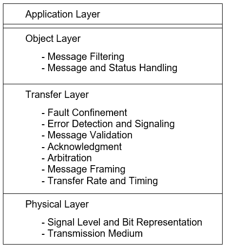
Layered Structure of a CAN Node
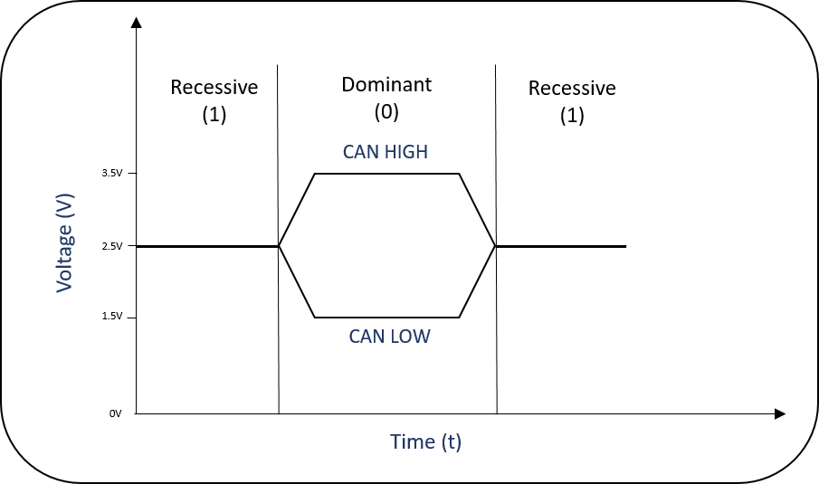
CAN Bus Signal Levels
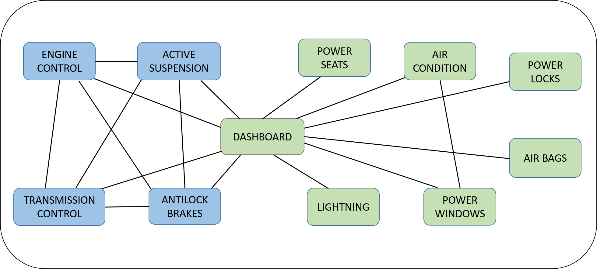
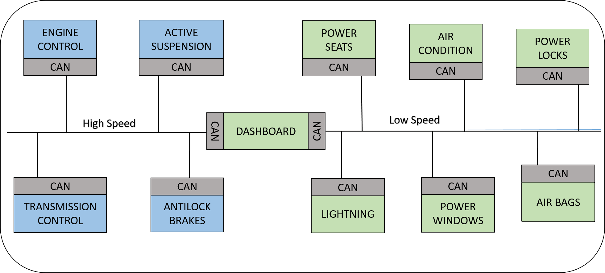
The CAN Bus
CAN bus is a broadcast type of bus which means that all nodes can receive all transmitted messages. There is no way to send messages to just a specific node.
CAN hardware provides local filtering of messages. The node which is user of the message can only react or give acknowledgment to the received message.
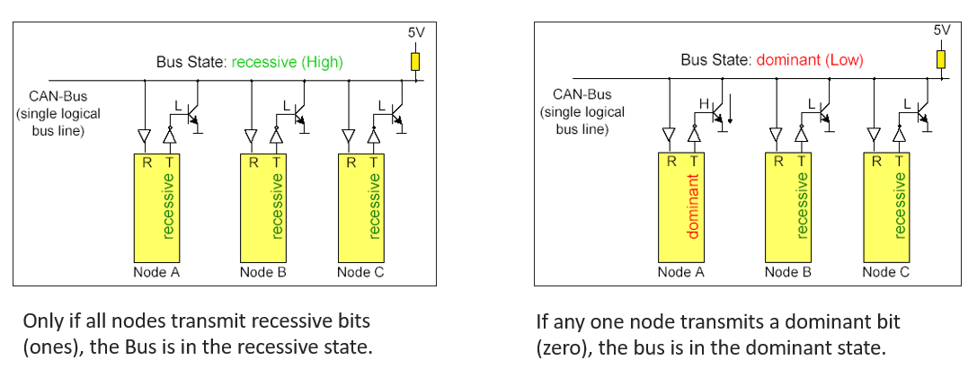
CAN Bus characteristics – Wired AND logic
CAN Bus Characteristics
CAN Frames
There are four types of frames in CAN Protocol:
- Data Frame (Widely used frame type)
- Remote Frame
- Error Frame
- Overload Frame
Data Frame
CAN data frame is widely used than other frame types .
There are two types of a data frame :
- Standard frame (11-bit Identifier)
- Extended frame (29-bit Identifier)
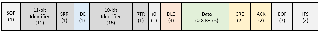
1) CAN Standard Frame (11-Bit Identifier) :
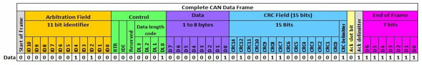
The CAN frame format for Standard frame is:

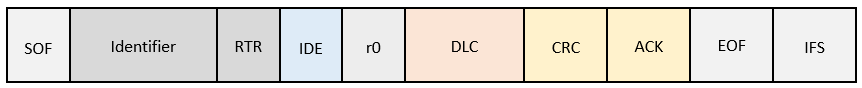
2) Extended Frame (29-Bit Identifier)
The CAN frame format for Extended frame is:
CAN Protocol Frame field details
- SOF – Start of Frame – 1 bit (Dominant)
- Arbitration Field – 11-bit Identifier, 1-bit RTR (or) 11 bit, 1 SRR, 1 IDE, 18 bit, 1 RTR
- Identifier – A message identifier sets the priority of the data frame
- RTR – Remote Transmission Request (data frame or remote frame) (1 bit)
- SRR – Substitute Remote Request
- Control Field – User Defined functions
- IDE – Identifier Extension bit means that a standard CAN Identifier with not extension
- r0 – Reserved bit (for possible use by future standard amendment)
- DLC – The 4-bit data length code (DLC) contains the number of bytes of data transmission
- Data Field – Data up to 64 bits of application data
- CRC Field – The 16-bit (15 bits plus delimiter) cyclic redundancy check (CRC) contains the checksum (number of bits transmitted) of the preceding application data for error detection.
- ACK Field – Receivers Acknowledgement
- EOF – End of Frame (7 bit – Recessive)
- IFS – This 7-bit interframe space (IFS) contains the time required by the controller to move a correctly
- received frame to its proper position in a message buffer area.
Remote Frame
CAN remote frame is the same as the data frame, but there are two main differences as below:
- The RTR bit in the arbitration field is recessive
- Remote frame doesn’t contain data field
The data length code field should contain the length of the expected response message otherwise the arbitration will not work.
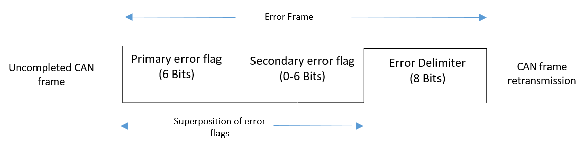
Error Frame
CAN Error frame is the special type of frame in CAN which violates the framing rules of a CAN message.
Error frame is transmits when a node detects a fault and will cause all other nodes to detect a fault – so they will send Error Frames, too.
The transmitter will then automatically try to retransmit the message. There is an elaborate scheme of error counters that ensures that a node can’t destroy the bus traffic by repeatedly transmitting Error Frames.
The Error Frame consists of an Error Flag, which is 6 bits of the same value (thus violating the bit-stuffing rule), and an Error Delimiter, which is 8 recessive bits.
The Error Delimiter provides some space in which the other nodes on the bus can send their Error Flags when they detect the first Error Flag.
Overload Frame
CAN overload frame is a special type of frame in CAN that introduces an additional delay between the data frame or remote frame when the CAN node receives messages faster than it can process that data.
The overload frame consists of two fields six dominant bits including an overload flag and an overload delimiter consisting of eight recessive bits.
Bus Access and Arbitration – CSMA/CD AMP (Arbitration on Message Priority)
CAN Arbitration
is the process to take control of the bus. Carries Sense means before transmission of the message CAN nodes monitor or observe the bus.
When two or more than two CAN nodes start communication, then SOF (Dominant) bit transmission happens from the nodes. this situation is called as Multiple Access.
If two nodes start transmitting at the same time then there is a situation of a collision. To solve this problem CAN uses Collision Detection and bitwise arbitration.
To understand arbitration in CAN let’s understand how data is transmission happens in CAN. Data is transmitted by nodes on the bus in form of frames. The frame has multiple fields but we are only interested in the first two fields, SOF and Identifier.
SOF is a bit used to signal start of a frame to all other nodes on the bus. The 2nd field is the Identifier which is an identifier for the type of message to be transmitted in the frame.
The lower the identifier higher the priority of the message. MSB is always transmitted first on the bus. CAN bus has two states a recessive state (logic level 1) and a dominant state (logic level 0).
The bus is always in the recessive state by default (i.e. using pull-up resistors), so when a node has to transmit one it leaves the bus in the default state, and when it has to transmit zero it drive the bus to the dominant state.
Take two nodes A and B that start transmitting at the same time Node A has identifier 48 while node B has identifier 56. When both transmit the 8th-bit Node B observes that its recessive 1 has been overridden by a dominant 0. So it stops transmitting and node A continues with its Frame transmission which is revived by all the nodes on the bus.
CAN Protocol Errors
There are five types of errors in CAN protocol.
- BIT Error
- STUFF Error
- CRC Error
- FORM Error
- ACK Error
BIT Error
A CAN node that is sending a bit on the bus also monitors that bit. When the bit value monitored is different than the bit value sent then BIT Error has to be detected.
When there is a ‘recessive’ stuffed bit in ARBITRATION Field or during the ACK SLOT and the ‘dominant’ bit value is monitored then there is an exception for the BIT Error.
STUFF Error
A STUFF Error has to be detected when there are 6 consecutive bits of equal value are detected in a message. It should be addressed using the bit stuffing method.
CRC Error
When a CAN message is transmitted on the bus it contains the CRC field which is the result of the CRC calculation done by the transmitter.
When the receiver receives a message it recalculates the CRC using the same calculation method used by the transmitter and if there is a difference between received CRC and calculated CRC this scenario is detected as CRC Error.
FORM Error
CAN message contains some fixed-format fields like CRC Delimiter, ACK Delimiter, End Of Frame, etc. the value of this field is always recessive but when any of this field bit is detected as dominant then it will be treated as FORM Error. That means it violates the format of the CAN message.
ACK Error
ACK field contains two bits ACK SLOT and ACK Delimiter. Whenever a message is transmitted ACK SLOT bit is recessive which is transmitted by the transmitter and it will wait for the dominant bit at the same field from the receiver if it doesn’t receive the dominant bit then it will be treated as an ACK Error.
Error confinement / Fault confinement
A node may be in one of the three states: error-active, error-passive, and bus-off. A CAN node uses an error counter to control the transition among these three states.
CAN protocol uses 12 rules to control the increment and decrement of the error counter.
When the error count is less than 128, a node is in an error-active state. if the error count equals or exceeds 128 but is not higher than 255, the node is in an error-passive state. When the error count equals or exceeds 256, the node is in a bus-off state.
An error-active node will transmit an active-error frame when detecting an error. An error-passive node will transmit a passive-error frame when detecting an error. A bus-off node is not allowed to take part in bus communication.
Bus Off Recovery
How to calculate CAN Bus Load?
CAN bus load is nothing but the percentage of bus capacity used.
i.e. Bus Load = ((Used Capacity / Max Capacity) * 100) in percent. Let’s see the below example for better understanding.
Considering standard identifier a CAN frame consists of:
- 1 bit SOF
- 11 bit Identifier
- 1 bit RTR
- 6 bit Control field
- 0-64 bit Data field
- 16 bit CRC field
- 2 bit ACK field
- 7 bit EOF
- 3 bit IFS
- Bit stuffing may be possible we are considering 19 bits to calculation purpose.
Let’s consider we want to send the frames on the bus at a 500kbps baud rate.
- 5 ms : 10 frames
- 10 ms : 5 frames
- 100 ms : 2 frames
considering 8 bytes od Data the total number of bits to be transmitted are 111 + 19 = 130 bits/frame
- 1/0.005 * 10 * 130 = 2,60,000 bits
- 1/0.010 * 5 * 130 = 65,000 bits
- 1/0.100 * 2 * 130 = 2600 bits
Total no of bits per second = 260000 + 65000 + 2600 = 3,27,600 bits/second
Bus Load = (3,27,600 / 5,00,000) * 100 = 65.52 %